8 Assemblies
A bracket and two pins, exported as one file of 335 records. Where the tree is, where the positions are, why they are kept apart, and the second way exporters do it.
The clamp is the bracket of Section 11.5 with two pins standing on it: one at x = 15, one at x = 45, both on the top face (Figure 8.1). As a STEP file it has three products but only two solids’ worth of geometry — the pin’s geometry appears once, not twice — and about forty records of structure that say how they fit together. This chapter is about those forty.
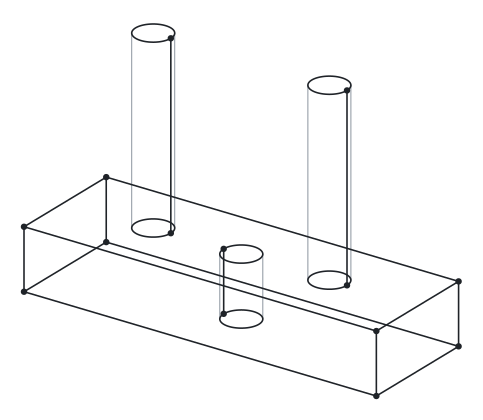
clamp.step, drawn by placing each component where the file’s transformations put it: the bracket once, the pin twice.
8.1 Three product chains
The file opens the way every file does, with a product chain. Then it has two more:
#5 = PRODUCT_DEFINITION('design','',#6,#9);
#7 = PRODUCT('CLAMP-ASSY','CLAMP-ASSY','',(#8));
    ...
#35 = PRODUCT_DEFINITION('design','',#36,#39);
#37 = PRODUCT('bracket','bracket','',(#38));
    ...
#243 = PRODUCT_DEFINITION('design','',#244,#247);
#245 = PRODUCT('pin-1','pin-1','',(#246));
Referred to above: 6 records from clamp.step
#2 = APPLICATION_CONTEXT(
  'core data for automotive mechanical design processes');
#6 = PRODUCT_DEFINITION_FORMATION('','',#7);
#8 = PRODUCT_CONTEXT('',#2,'mechanical');
#9 = PRODUCT_DEFINITION_CONTEXT('part definition',#2,'design');
#38 = PRODUCT_CONTEXT('',#2,'mechanical');
#246 = PRODUCT_CONTEXT('',#2,'mechanical');Each has its own formation, its own pair of contexts, its own category record. #5 is the assembly’s definition, #35 the bracket’s, #243 the pin’s. Nothing in these records relates them to one another. The pin’s product is called 'pin-1' rather than 'pin' — the exporter took the name of the first instance it met as the name of the part — which is the kind of thing you learn to expect from assembly exports and which the structure below does not depend on.
Each product also has its shape. The bracket’s and pin’s are ADVANCED_s containing solids, exactly as in the single-part files. The assembly’s is different:
#3 = SHAPE_DEFINITION_REPRESENTATION(#4,#10);
#4 = PRODUCT_DEFINITION_SHAPE('','',#5);
#10 = SHAPE_REPRESENTATION('',(#11,#15,#19,#23),#27);
#11 = AXIS2_PLACEMENT_3D('',#12,#13,#14);        /* origin */
#15 = AXIS2_PLACEMENT_3D('',#16,#17,#18);        /* (0,0,0): the bracket goes here */
#19 = AXIS2_PLACEMENT_3D('',#20,#21,#22);        /* (15,10,10): pin-1 goes here */
#23 = AXIS2_PLACEMENT_3D('',#24,#25,#26);        /* (45,10,10): pin-2 goes here */
Referred to above: 23 records from clamp.step
#2 = APPLICATION_CONTEXT(
  'core data for automotive mechanical design processes');
#5 = PRODUCT_DEFINITION('design','',#6,#9);
#6 = PRODUCT_DEFINITION_FORMATION('','',#7);
#7 = PRODUCT('CLAMP-ASSY','CLAMP-ASSY','',(#8));
#8 = PRODUCT_CONTEXT('',#2,'mechanical');
#9 = PRODUCT_DEFINITION_CONTEXT('part definition',#2,'design');
#12 = CARTESIAN_POINT('',(0.,0.,0.));
#13 = DIRECTION('',(0.,0.,1.));
#14 = DIRECTION('',(1.,0.,-0.));
#16 = CARTESIAN_POINT('',(0.,0.,0.));
#17 = DIRECTION('',(0.,0.,1.));
#18 = DIRECTION('',(1.,0.,-0.));
#20 = CARTESIAN_POINT('',(15.,10.,10.));
#21 = DIRECTION('',(0.,0.,1.));
#22 = DIRECTION('',(1.,0.,-0.));
#24 = CARTESIAN_POINT('',(45.,10.,10.));
#25 = DIRECTION('',(0.,0.,1.));
#26 = DIRECTION('',(1.,0.,-0.));
#27 = ( GEOMETRIC_REPRESENTATION_CONTEXT(3)
GLOBAL_UNCERTAINTY_ASSIGNED_CONTEXT((#31)) GLOBAL_UNIT_ASSIGNED_CONTEXT(
(#28,#29,#30)) REPRESENTATION_CONTEXT('Context #1',
  '3D Context with UNIT and UNCERTAINTY') );
#28 = ( LENGTH_UNIT() NAMED_UNIT(*) SI_UNIT(.MILLI.,.METRE.) );
#29 = ( NAMED_UNIT(*) PLANE_ANGLE_UNIT() SI_UNIT($,.RADIAN.) );
#30 = ( NAMED_UNIT(*) SI_UNIT($,.STERADIAN.) SOLID_ANGLE_UNIT() );
#31 = UNCERTAINTY_MEASURE_WITH_UNIT(LENGTH_MEASURE(1.E-07),#28,
  'distance_accuracy_value','confusion accuracy');
The assembly has no solid. Its shape representation is a plain SHAPE_ whose items are four coordinate frames: its own origin and one target position for each child. The geometry of an assembly is the geometry of its children, placed. This representation is the assembly’s coordinate space, and the placements in it are the only numbers in the whole structure.
8.2 The tree: NEXT_ASSEMBLY_USAGE_OCCURRENCE
The parent–child relationships are three records:
#239 = NEXT_ASSEMBLY_USAGE_OCCURRENCE('1','bracket','',#5,#35,$);
#311 = NEXT_ASSEMBLY_USAGE_OCCURRENCE('2','pin-1','',#5,#243,$);
#317 = NEXT_ASSEMBLY_USAGE_OCCURRENCE('3','pin-2','',#5,#243,$);
Referred to above: 16 records from clamp.step
#2 = APPLICATION_CONTEXT(
  'core data for automotive mechanical design processes');
#5 = PRODUCT_DEFINITION('design','',#6,#9);
#6 = PRODUCT_DEFINITION_FORMATION('','',#7);
#7 = PRODUCT('CLAMP-ASSY','CLAMP-ASSY','',(#8));
#8 = PRODUCT_CONTEXT('',#2,'mechanical');
#9 = PRODUCT_DEFINITION_CONTEXT('part definition',#2,'design');
#35 = PRODUCT_DEFINITION('design','',#36,#39);
#36 = PRODUCT_DEFINITION_FORMATION('','',#37);
#37 = PRODUCT('bracket','bracket','',(#38));
#38 = PRODUCT_CONTEXT('',#2,'mechanical');
#39 = PRODUCT_DEFINITION_CONTEXT('part definition',#2,'design');
#243 = PRODUCT_DEFINITION('design','',#244,#247);
#244 = PRODUCT_DEFINITION_FORMATION('','',#245);
#245 = PRODUCT('pin-1','pin-1','',(#246));
#246 = PRODUCT_CONTEXT('',#2,'mechanical');
#247 = PRODUCT_DEFINITION_CONTEXT('part definition',#2,'design');
The schema, through three levels of inheritance:
ENTITY product_definition_relationship;
  id                          : identifier;
  name                        : label;
  description                 : OPTIONAL text;
  relating_product_definition : product_definition;     -- the parent
  related_product_definition  : product_definition;     -- the child
END_ENTITY;

ENTITY product_definition_usage
  SUBTYPE OF (product_definition_relationship);
END_ENTITY;

ENTITY assembly_component_usage
  SUBTYPE OF (product_definition_usage);
  reference_designator : OPTIONAL identifier;
END_ENTITY;

ENTITY next_assembly_usage_occurrence
  SUBTYPE OF (assembly_component_usage);
END_ENTITY;
NEXT_ declares nothing of its own; all six parameters are inherited. Six parameters: an id, a name, a description, the relating (parent) definition, the related (child) definition, and an optional reference designator. One record is one occurrence of one child inside one parent. These records form a directed acyclic graph of product definitions, with a separate edge for each usage. The occurrence tree is that graph expanded from a root; a reused subassembly is expanded once per occurrence, each with its own world transform. There is no record for “the assembly structure” as a whole; there are only edges, and the tree is whatever they add up to.
Three things to notice.
#311 and #317 both have #243 as their child. The pin is defined once and used twice. This is the distinction a bill of materials rests on: one product definition, two occurrences. The BOM line for the pin has quantity 2 because two NAUOs point at it, and there is one pin geometry in the file, not two.
The name attribute carries the instance name — 'pin-1', 'pin-2' — which is how the CAD system distinguished the two occurrences in its tree. The part’s own name is on the PRODUCT record. In this file they collide ('pin-1' is both the product name and the first instance name) because of the exporter’s naming choice; in a SolidWorks or NX export the product would be 'PIN' and the instances 'PIN-1' and 'PIN-2'.
The reference_ is $. It is meant for the position label on an electrical schematic or a drawing balloon — 'R12', 'B3' — and most mechanical exporters leave it empty.
A tree with only NAUOs is unplaced. The NAUOs say nothing about where each child sits; a viewer that draws them at the parent’s origin is falling back, not reading a placement. Position is a separate structure, attached to each NAUO from the side.
8.3 The position: five records per occurrence
For the bracket:
#238 = PRODUCT_DEFINITION_SHAPE('Placement','Placement of an item',#239);
#235 = CONTEXT_DEPENDENT_SHAPE_REPRESENTATION(#236,#238);
#236 = ( REPRESENTATION_RELATIONSHIP('','',#40,#10)
         REPRESENTATION_RELATIONSHIP_WITH_TRANSFORMATION(#237)
         SHAPE_REPRESENTATION_RELATIONSHIP() );
#237 = ITEM_DEFINED_TRANSFORMATION('','',#11,#15);
#15 = AXIS2_PLACEMENT_3D('',#16,#17,#18);        /* in the assembly's representation */
Referred to above: 228 records from clamp.step
#2 = APPLICATION_CONTEXT(
  'core data for automotive mechanical design processes');
#5 = PRODUCT_DEFINITION('design','',#6,#9);
#6 = PRODUCT_DEFINITION_FORMATION('','',#7);
#7 = PRODUCT('CLAMP-ASSY','CLAMP-ASSY','',(#8));
#8 = PRODUCT_CONTEXT('',#2,'mechanical');
#9 = PRODUCT_DEFINITION_CONTEXT('part definition',#2,'design');
#10 = SHAPE_REPRESENTATION('',(#11,#15,#19,#23),#27);
#11 = AXIS2_PLACEMENT_3D('',#12,#13,#14);
#12 = CARTESIAN_POINT('',(0.,0.,0.));
#13 = DIRECTION('',(0.,0.,1.));
#14 = DIRECTION('',(1.,0.,-0.));
#16 = CARTESIAN_POINT('',(0.,0.,0.));
#17 = DIRECTION('',(0.,0.,1.));
#18 = DIRECTION('',(1.,0.,-0.));
#19 = AXIS2_PLACEMENT_3D('',#20,#21,#22);
#20 = CARTESIAN_POINT('',(15.,10.,10.));
#21 = DIRECTION('',(0.,0.,1.));
#22 = DIRECTION('',(1.,0.,-0.));
#23 = AXIS2_PLACEMENT_3D('',#24,#25,#26);
#24 = CARTESIAN_POINT('',(45.,10.,10.));
#25 = DIRECTION('',(0.,0.,1.));
#26 = DIRECTION('',(1.,0.,-0.));
#27 = ( GEOMETRIC_REPRESENTATION_CONTEXT(3)
GLOBAL_UNCERTAINTY_ASSIGNED_CONTEXT((#31)) GLOBAL_UNIT_ASSIGNED_CONTEXT(
(#28,#29,#30)) REPRESENTATION_CONTEXT('Context #1',
  '3D Context with UNIT and UNCERTAINTY') );
#28 = ( LENGTH_UNIT() NAMED_UNIT(*) SI_UNIT(.MILLI.,.METRE.) );
#29 = ( NAMED_UNIT(*) PLANE_ANGLE_UNIT() SI_UNIT($,.RADIAN.) );
#30 = ( NAMED_UNIT(*) SI_UNIT($,.STERADIAN.) SOLID_ANGLE_UNIT() );
#31 = UNCERTAINTY_MEASURE_WITH_UNIT(LENGTH_MEASURE(1.E-07),#28,
  'distance_accuracy_value','confusion accuracy');
#35 = PRODUCT_DEFINITION('design','',#36,#39);
#36 = PRODUCT_DEFINITION_FORMATION('','',#37);
#37 = PRODUCT('bracket','bracket','',(#38));
#38 = PRODUCT_CONTEXT('',#2,'mechanical');
#39 = PRODUCT_DEFINITION_CONTEXT('part definition',#2,'design');
#40 = ADVANCED_BREP_SHAPE_REPRESENTATION('',(#11,#41),#230);
#41 = MANIFOLD_SOLID_BREP('',#42);
#42 = CLOSED_SHELL('',(#43,#83,#114,#149,#173,#201,#213));
#43 = ADVANCED_FACE('',(#44),#78,.F.);
#44 = FACE_BOUND('',#45,.F.);
#45 = EDGE_LOOP('',(#46,#56,#64,#72));
#46 = ORIENTED_EDGE('',*,*,#47,.F.);
#47 = EDGE_CURVE('',#48,#50,#52,.T.);
#48 = VERTEX_POINT('',#49);
#49 = CARTESIAN_POINT('',(0.,0.,0.));
#50 = VERTEX_POINT('',#51);
#51 = CARTESIAN_POINT('',(0.,0.,10.));
#52 = LINE('',#53,#54);
#53 = CARTESIAN_POINT('',(0.,0.,0.));
#54 = VECTOR('',#55,1.);
#55 = DIRECTION('',(0.,0.,1.));
#56 = ORIENTED_EDGE('',*,*,#57,.T.);
#57 = EDGE_CURVE('',#48,#58,#60,.T.);
#58 = VERTEX_POINT('',#59);
#59 = CARTESIAN_POINT('',(0.,20.,0.));
#60 = LINE('',#61,#62);
#61 = CARTESIAN_POINT('',(0.,0.,0.));
#62 = VECTOR('',#63,1.);
#63 = DIRECTION('',(0.,1.,0.));
#64 = ORIENTED_EDGE('',*,*,#65,.T.);
#65 = EDGE_CURVE('',#58,#66,#68,.T.);
#66 = VERTEX_POINT('',#67);
#67 = CARTESIAN_POINT('',(0.,20.,10.));
#68 = LINE('',#69,#70);
#69 = CARTESIAN_POINT('',(0.,20.,0.));
#70 = VECTOR('',#71,1.);
#71 = DIRECTION('',(0.,0.,1.));
#72 = ORIENTED_EDGE('',*,*,#73,.F.);
#73 = EDGE_CURVE('',#50,#66,#74,.T.);
#74 = LINE('',#75,#76);
#75 = CARTESIAN_POINT('',(0.,0.,10.));
#76 = VECTOR('',#77,1.);
#77 = DIRECTION('',(0.,1.,0.));
#78 = PLANE('',#79);
#79 = AXIS2_PLACEMENT_3D('',#80,#81,#82);
#80 = CARTESIAN_POINT('',(0.,0.,0.));
#81 = DIRECTION('',(1.,0.,0.));
#82 = DIRECTION('',(0.,0.,1.));
#83 = ADVANCED_FACE('',(#84),#109,.F.);
#84 = FACE_BOUND('',#85,.F.);
#85 = EDGE_LOOP('',(#86,#94,#95,#103));
#86 = ORIENTED_EDGE('',*,*,#87,.F.);
#87 = EDGE_CURVE('',#48,#88,#90,.T.);
#88 = VERTEX_POINT('',#89);
#89 = CARTESIAN_POINT('',(60.,0.,0.));
#90 = LINE('',#91,#92);
#91 = CARTESIAN_POINT('',(0.,0.,0.));
#92 = VECTOR('',#93,1.);
#93 = DIRECTION('',(1.,0.,0.));
#94 = ORIENTED_EDGE('',*,*,#47,.T.);
#95 = ORIENTED_EDGE('',*,*,#96,.T.);
#96 = EDGE_CURVE('',#50,#97,#99,.T.);
#97 = VERTEX_POINT('',#98);
#98 = CARTESIAN_POINT('',(60.,0.,10.));
#99 = LINE('',#100,#101);
#100 = CARTESIAN_POINT('',(0.,0.,10.));
#101 = VECTOR('',#102,1.);
#102 = DIRECTION('',(1.,0.,0.));
#103 = ORIENTED_EDGE('',*,*,#104,.F.);
#104 = EDGE_CURVE('',#88,#97,#105,.T.);
#105 = LINE('',#106,#107);
#106 = CARTESIAN_POINT('',(60.,0.,0.));
#107 = VECTOR('',#108,1.);
#108 = DIRECTION('',(0.,0.,1.));
#109 = PLANE('',#110);
#110 = AXIS2_PLACEMENT_3D('',#111,#112,#113);
#111 = CARTESIAN_POINT('',(0.,0.,0.));
#112 = DIRECTION('',(0.,1.,0.));
#113 = DIRECTION('',(0.,0.,1.));
#114 = ADVANCED_FACE('',(#115,#133),#144,.T.);
#115 = FACE_BOUND('',#116,.T.);
#116 = EDGE_LOOP('',(#117,#118,#119,#127));
#117 = ORIENTED_EDGE('',*,*,#73,.F.);
#118 = ORIENTED_EDGE('',*,*,#96,.T.);
#119 = ORIENTED_EDGE('',*,*,#120,.T.);
#120 = EDGE_CURVE('',#97,#121,#123,.T.);
#121 = VERTEX_POINT('',#122);
#122 = CARTESIAN_POINT('',(60.,20.,10.));
#123 = LINE('',#124,#125);
#124 = CARTESIAN_POINT('',(60.,0.,10.));
#125 = VECTOR('',#126,1.);
#126 = DIRECTION('',(0.,1.,0.));
#127 = ORIENTED_EDGE('',*,*,#128,.F.);
#128 = EDGE_CURVE('',#66,#121,#129,.T.);
#129 = LINE('',#130,#131);
#130 = CARTESIAN_POINT('',(0.,20.,10.));
#131 = VECTOR('',#132,1.);
#132 = DIRECTION('',(1.,0.,0.));
#133 = FACE_BOUND('',#134,.T.);
#134 = EDGE_LOOP('',(#135));
#135 = ORIENTED_EDGE('',*,*,#136,.T.);
#136 = EDGE_CURVE('',#137,#137,#139,.T.);
#137 = VERTEX_POINT('',#138);
#138 = CARTESIAN_POINT('',(27.,10.,10.));
#139 = CIRCLE('',#140,3.);
#140 = AXIS2_PLACEMENT_3D('',#141,#142,#143);
#141 = CARTESIAN_POINT('',(30.,10.,10.));
#142 = DIRECTION('',(0.,0.,-1.));
#143 = DIRECTION('',(-1.,0.,0.));
#144 = PLANE('',#145);
#145 = AXIS2_PLACEMENT_3D('',#146,#147,#148);
#146 = CARTESIAN_POINT('',(0.,0.,10.));
#147 = DIRECTION('',(0.,0.,1.));
#148 = DIRECTION('',(1.,0.,0.));
#149 = ADVANCED_FACE('',(#150),#168,.T.);
#150 = FACE_BOUND('',#151,.T.);
#151 = EDGE_LOOP('',(#152,#160,#161,#162));
#152 = ORIENTED_EDGE('',*,*,#153,.F.);
#153 = EDGE_CURVE('',#58,#154,#156,.T.);
#154 = VERTEX_POINT('',#155);
#155 = CARTESIAN_POINT('',(60.,20.,0.));
#156 = LINE('',#157,#158);
#157 = CARTESIAN_POINT('',(0.,20.,0.));
#158 = VECTOR('',#159,1.);
#159 = DIRECTION('',(1.,0.,0.));
#160 = ORIENTED_EDGE('',*,*,#65,.T.);
#161 = ORIENTED_EDGE('',*,*,#128,.T.);
#162 = ORIENTED_EDGE('',*,*,#163,.F.);
#163 = EDGE_CURVE('',#154,#121,#164,.T.);
#164 = LINE('',#165,#166);
#165 = CARTESIAN_POINT('',(60.,20.,0.));
#166 = VECTOR('',#167,1.);
#167 = DIRECTION('',(0.,0.,1.));
#168 = PLANE('',#169);
#169 = AXIS2_PLACEMENT_3D('',#170,#171,#172);
#170 = CARTESIAN_POINT('',(0.,20.,0.));
#171 = DIRECTION('',(0.,1.,0.));
#172 = DIRECTION('',(0.,0.,1.));
#173 = ADVANCED_FACE('',(#174,#185),#196,.F.);
#174 = FACE_BOUND('',#175,.F.);
#175 = EDGE_LOOP('',(#176,#177,#178,#184));
#176 = ORIENTED_EDGE('',*,*,#57,.F.);
#177 = ORIENTED_EDGE('',*,*,#87,.T.);
#178 = ORIENTED_EDGE('',*,*,#179,.T.);
#179 = EDGE_CURVE('',#88,#154,#180,.T.);
#180 = LINE('',#181,#182);
#181 = CARTESIAN_POINT('',(60.,0.,0.));
#182 = VECTOR('',#183,1.);
#183 = DIRECTION('',(0.,1.,0.));
#184 = ORIENTED_EDGE('',*,*,#153,.F.);
#185 = FACE_BOUND('',#186,.F.);
#186 = EDGE_LOOP('',(#187));
#187 = ORIENTED_EDGE('',*,*,#188,.T.);
#188 = EDGE_CURVE('',#189,#189,#191,.T.);
#189 = VERTEX_POINT('',#190);
#190 = CARTESIAN_POINT('',(27.,10.,0.));
#191 = CIRCLE('',#192,3.);
#192 = AXIS2_PLACEMENT_3D('',#193,#194,#195);
#193 = CARTESIAN_POINT('',(30.,10.,0.));
#194 = DIRECTION('',(0.,0.,-1.));
#195 = DIRECTION('',(-1.,0.,0.));
#196 = PLANE('',#197);
#197 = AXIS2_PLACEMENT_3D('',#198,#199,#200);
#198 = CARTESIAN_POINT('',(0.,0.,0.));
#199 = DIRECTION('',(0.,0.,1.));
#200 = DIRECTION('',(1.,0.,0.));
#201 = ADVANCED_FACE('',(#202),#208,.T.);
#202 = FACE_BOUND('',#203,.T.);
#203 = EDGE_LOOP('',(#204,#205,#206,#207));
#204 = ORIENTED_EDGE('',*,*,#104,.F.);
#205 = ORIENTED_EDGE('',*,*,#179,.T.);
#206 = ORIENTED_EDGE('',*,*,#163,.T.);
#207 = ORIENTED_EDGE('',*,*,#120,.F.);
#208 = PLANE('',#209);
#209 = AXIS2_PLACEMENT_3D('',#210,#211,#212);
#210 = CARTESIAN_POINT('',(60.,0.,0.));
#211 = DIRECTION('',(1.,0.,0.));
#212 = DIRECTION('',(0.,0.,1.));
#213 = ADVANCED_FACE('',(#214),#225,.F.);
#214 = FACE_BOUND('',#215,.F.);
#215 = EDGE_LOOP('',(#216,#217,#223,#224));
#216 = ORIENTED_EDGE('',*,*,#188,.F.);
#217 = ORIENTED_EDGE('',*,*,#218,.F.);
#218 = EDGE_CURVE('',#137,#189,#219,.T.);
#219 = LINE('',#220,#221);
#220 = CARTESIAN_POINT('',(27.,10.,10.));
#221 = VECTOR('',#222,1.);
#222 = DIRECTION('',(0.,0.,-1.));
#223 = ORIENTED_EDGE('',*,*,#136,.T.);
#224 = ORIENTED_EDGE('',*,*,#218,.T.);
#225 = CYLINDRICAL_SURFACE('',#226,3.);
#226 = AXIS2_PLACEMENT_3D('',#227,#228,#229);
#227 = CARTESIAN_POINT('',(30.,10.,10.));
#228 = DIRECTION('',(0.,0.,-1.));
#229 = DIRECTION('',(-1.,0.,0.));
#230 = ( GEOMETRIC_REPRESENTATION_CONTEXT(3)
GLOBAL_UNCERTAINTY_ASSIGNED_CONTEXT((#234)) GLOBAL_UNIT_ASSIGNED_CONTEXT
((#231,#232,#233)) REPRESENTATION_CONTEXT('Context #1',
  '3D Context with UNIT and UNCERTAINTY') );
#231 = ( LENGTH_UNIT() NAMED_UNIT(*) SI_UNIT(.MILLI.,.METRE.) );
#232 = ( NAMED_UNIT(*) PLANE_ANGLE_UNIT() SI_UNIT($,.RADIAN.) );
#233 = ( NAMED_UNIT(*) SI_UNIT($,.STERADIAN.) SOLID_ANGLE_UNIT() );
#234 = UNCERTAINTY_MEASURE_WITH_UNIT(LENGTH_MEASURE(1.E-07),#231,
  'distance_accuracy_value','confusion accuracy');
#239 = NEXT_ASSEMBLY_USAGE_OCCURRENCE('1','bracket','',#5,#35,$);Reading it from the NAUO outward:
#238 is a PRODUCT_ whose definition is the NAUO #239 rather than a product definition. Chapter 7 said the definition attribute is a SELECT that admits either; this is the other case. It means: the occurrence of the bracket in the clamp has a shape. The strings 'Placement' and 'Placement of an item' are this exporter’s habit; others write ''.
#235 is the bridge. CONTEXT_ has two attributes: a representation_ and a represented_. It ties the occurrence-shape #238 to a relationship between two representations.
#236 is a complex instance you can now read. It is a REPRESENTATION_ between #40 (the bracket’s shape representation) and #10 (the assembly’s); it is with a transformation, #237; and it is specifically a shape representation relationship. REPRESENTATION_ and SHAPE_ are sibling subtypes of REPRESENTATION_, and no single leaf names the pair. So the instance is written externally, with their shared supertype listed as well, and the blocks in alphabetical order.
#237 is the transformation, and it contains no numbers. ITEM_ has two attributes beyond name and description: transform_ and transform_, both representation items. Here they are two axis placements: #11, the origin frame that sits in the bracket’s own representation, and #15, a frame in the assembly’s representation. The transformation is whatever rigid motion carries frame #11 onto frame #15. Put the bracket’s origin at #15’s origin, its Z along #15’s Z, its X along #15’s X.
#15 is that target frame — at (0, 0, 0) with identity orientation, because the bracket sits at the assembly origin. For pin-1 the corresponding record is #19, at (15, 10, 10); for pin-2 it is #23, at (45, 10, 10). Those three points are the only coordinates in the assembly structure.
So the NAUO says what goes inside what, and its placement chain says where, and the two are joined through #238 only — and only in the inverse direction, since #238 points at the NAUO and nothing points at #238 except #235, which nothing points at either. From a NAUO, finding its position means asking “what PRODUCT_ refers to me?” and then “what CONTEXT_ refers to that?” — two more walks against the arrows before the references turn forward.
8.4 The frame as a transform
#19 = AXIS2_PLACEMENT_3D('',#20,#21,#22);
#20 = CARTESIAN_POINT('',(15.,10.,10.));
#21 = DIRECTION('',(0.,0.,1.));
#22 = DIRECTION('',(1.,0.,-0.));
An AXIS2_ has a location, an optional axis and an optional ref_. The axis, normalised, is the frame’s Z; the reference direction is projected perpendicular to Z and normalised to give X; Y is Z × X. If the axis is omitted, Z is (0, 0, 1). If the reference direction is omitted, Part 42’s first_ projects (1, 0, 0), or (0, 1, 0) when Z is itself (±1, 0, 0): the fallback is specified, not an arbitrary perpendicular. Three references, and the result is a complete right-handed coordinate frame — which is to say a rigid transformation: a rotation plus a translation, with no scaling and no reflection.
Placing pin-1, then, means: take the pin’s geometry, whose coordinates are in its own frame (#11 in the pin’s representation — the pin stands on the origin with its axis along Z), and move it so that frame lands on #19. Translation by (15, 10, 10), no rotation. The pin’s base circle, at z = 0 in its own file, is at z = 10 in the assembly: the top of the bracket.
ITEM_ does not say which of its two items is the child’s origin and which is the target. In AP242 the schema already ties the items to the representations: transform_ must be used in rep_ and transform_ in rep_. What no schema says, and the CAx Implementor Forum’s recommended practice does, is that rep_ is the child (component) and rep_ the parent (assembly). This file follows both conventions: #236 has rep_ (bracket) and rep_ (assembly); #237 has item 1 in the bracket’s representation and item 2 in the assembly’s. Not every exporter does. A robust reader does not trust the order; it finds the frame that belongs to only one of the two representations — usually the target in the parent — and orients the transformation from that, because the child’s origin frame is often shared by every representation in the file. When both frames are the identity, as for the bracket here, getting it backwards is invisible — which is how the bug survives.
8.5 Walking the tree
With the records understood, the procedure for reconstructing the assembly:
- Find the roots. A root is a product definition that is nobody’s
related_. Hereproduct_ definition #5. A file may have several roots (a multi-body export, or several unrelated assemblies). - Children of a definition are the NAUOs whose
relating_is it. Forproduct_ definition #5:#239,#311,#317. - For each NAUO, find the
PRODUCT_that points at it, theDEFINITION_ SHAPE CONTEXT_that points at that, and from there forward to the relationship, the transformation, and the two frames. If the chain is absent, try the mapped-item route below; if there is neither, readers place the child at identity, which is a convention of readers rather than a statement in the file.DEPENDENT_ SHAPE_ REPRESENTATION - Geometry of a definition is found through its own
PRODUCT_andDEFINITION_ SHAPE SHAPE_, as in Chapter 7.DEFINITION_ REPRESENTATION - World position of a child = parent’s world transform composed with the local one. Recurse into the child’s own NAUOs.
Convert translations and geometry to consistent length units before composing transforms between contexts. Detect cycles along the active recursion path, but do not use a global visited set to suppress repeated definitions: that would drop legitimate occurrences and undercount a reused subassembly’s children.
The bill of materials is steps 1, 2 and 5 without the geometry: walk the tree, group occurrences by related_, count. For the clamp: bracket × 1, pin × 2.
Two sharings in this file are worth noticing because they are typical and because they catch tools that copy records around. The origin frame #11 is an item of all three shape representations — #10, #40 and #248 — and is transform_ in all three transformations. One record, six roles. And the three geometric contexts (#27, #230, #302) are textually identical but distinct records, one per product; each representation points at its own.
This exporter writes 'part' for all three products, including the assembly (#32 points at #7, CLAMP-ASSY). That is not a defect: these are AP214 files, and AP214’s list of category names has no 'assembly' in it. AP203 and AP242 have no such list, and require 'assembly' only on a product whose definition is declared an assembly definition; some exporters omit the category entirely. Either way the category is no substitute for walking the NEXT_ records. The NAUOs are the truth: a definition with children is an assembly whatever its category says.
8.6 The other way: MAPPED_ITEM
Everything above is the product-structure way of placing components, and it is what the recommended practices call for. There is a second, older mechanism that some exporters use for assemblies and some for repeated geometry within a part, and a reader must know both.
#400 = MAPPED_ITEM('',#401,#19);
#401 = REPRESENTATION_MAP(#11,#248);
Referred to above: 67 records from clamp.step
#11 = AXIS2_PLACEMENT_3D('',#12,#13,#14);
#12 = CARTESIAN_POINT('',(0.,0.,0.));
#13 = DIRECTION('',(0.,0.,1.));
#14 = DIRECTION('',(1.,0.,-0.));
#19 = AXIS2_PLACEMENT_3D('',#20,#21,#22);
#20 = CARTESIAN_POINT('',(15.,10.,10.));
#21 = DIRECTION('',(0.,0.,1.));
#22 = DIRECTION('',(1.,0.,-0.));
#248 = ADVANCED_BREP_SHAPE_REPRESENTATION('',(#11,#249),#302);
#249 = MANIFOLD_SOLID_BREP('',#250);
#250 = CLOSED_SHELL('',(#251,#284,#293));
#251 = ADVANCED_FACE('',(#252),#279,.T.);
#252 = FACE_BOUND('',#253,.F.);
#253 = EDGE_LOOP('',(#254,#264,#271,#272));
#254 = ORIENTED_EDGE('',*,*,#255,.T.);
#255 = EDGE_CURVE('',#256,#258,#260,.T.);
#256 = VERTEX_POINT('',#257);
#257 = CARTESIAN_POINT('',(3.,0.,0.));
#258 = VERTEX_POINT('',#259);
#259 = CARTESIAN_POINT('',(3.,0.,30.));
#260 = LINE('',#261,#262);
#261 = CARTESIAN_POINT('',(3.,0.,0.));
#262 = VECTOR('',#263,1.);
#263 = DIRECTION('',(0.,0.,1.));
#264 = ORIENTED_EDGE('',*,*,#265,.T.);
#265 = EDGE_CURVE('',#258,#258,#266,.T.);
#266 = CIRCLE('',#267,3.);
#267 = AXIS2_PLACEMENT_3D('',#268,#269,#270);
#268 = CARTESIAN_POINT('',(0.,0.,30.));
#269 = DIRECTION('',(0.,0.,1.));
#270 = DIRECTION('',(1.,0.,0.));
#271 = ORIENTED_EDGE('',*,*,#255,.F.);
#272 = ORIENTED_EDGE('',*,*,#273,.F.);
#273 = EDGE_CURVE('',#256,#256,#274,.T.);
#274 = CIRCLE('',#275,3.);
#275 = AXIS2_PLACEMENT_3D('',#276,#277,#278);
#276 = CARTESIAN_POINT('',(0.,0.,0.));
#277 = DIRECTION('',(0.,0.,1.));
#278 = DIRECTION('',(1.,0.,0.));
#279 = CYLINDRICAL_SURFACE('',#280,3.);
#280 = AXIS2_PLACEMENT_3D('',#281,#282,#283);
#281 = CARTESIAN_POINT('',(0.,0.,0.));
#282 = DIRECTION('',(-0.,-0.,-1.));
#283 = DIRECTION('',(1.,0.,0.));
#284 = ADVANCED_FACE('',(#285),#288,.F.);
#285 = FACE_BOUND('',#286,.F.);
#286 = EDGE_LOOP('',(#287));
#287 = ORIENTED_EDGE('',*,*,#273,.T.);
#288 = PLANE('',#289);
#289 = AXIS2_PLACEMENT_3D('',#290,#291,#292);
#290 = CARTESIAN_POINT('',(-1.709300165674E-16,-8.51133553645E-18,0.));
#291 = DIRECTION('',(0.,0.,1.));
#292 = DIRECTION('',(1.,0.,-0.));
#293 = ADVANCED_FACE('',(#294),#297,.T.);
#294 = FACE_BOUND('',#295,.T.);
#295 = EDGE_LOOP('',(#296));
#296 = ORIENTED_EDGE('',*,*,#265,.T.);
#297 = PLANE('',#298);
#298 = AXIS2_PLACEMENT_3D('',#299,#300,#301);
#299 = CARTESIAN_POINT('',(-1.709300165674E-16,-8.51133553645E-18,30.));
#300 = DIRECTION('',(0.,0.,1.));
#301 = DIRECTION('',(1.,0.,-0.));
#302 = ( GEOMETRIC_REPRESENTATION_CONTEXT(3)
GLOBAL_UNCERTAINTY_ASSIGNED_CONTEXT((#306)) GLOBAL_UNIT_ASSIGNED_CONTEXT
((#303,#304,#305)) REPRESENTATION_CONTEXT('Context #1',
  '3D Context with UNIT and UNCERTAINTY') );
#303 = ( LENGTH_UNIT() NAMED_UNIT(*) SI_UNIT(.MILLI.,.METRE.) );
#304 = ( NAMED_UNIT(*) PLANE_ANGLE_UNIT() SI_UNIT($,.RADIAN.) );
#305 = ( NAMED_UNIT(*) SI_UNIT($,.STERADIAN.) SOLID_ANGLE_UNIT() );
#306 = UNCERTAINTY_MEASURE_WITH_UNIT(LENGTH_MEASURE(1.E-07),#303,
'distance_accuracy_value','confusion accuracy');A MAPPED_ is a representation item — it sits in the parent’s SHAPE_, next to the axis placements — that says “the representation #248, whose origin is #11, placed at frame #19.” The REPRESENTATION_ pairs a source representation with its origin; the mapped item pairs the map with a target. Same information as #235–#237, two records instead of three, and no PRODUCT_ on the NAUO.
When an exporter uses mapped items for an assembly, the NAUOs are still written — the product structure is unchanged — but the positions are in the parent’s representation items rather than hanging off the NAUOs. A reader that only knows the CONTEXT_ route will find no placements and put every child at the origin. If a NAUO has no placement chain, look in the parent’s shape representation for MAPPED_s whose map’s source is the child’s representation. That finds the placements; when several occurrences share one child representation, nothing in the file says which mapped item is which NAUO, and the pairing has to be left open.
Mapped items also appear where there is no assembly at all: a repeated sub-model, or a block of annotation geometry drawn once and placed a dozen times. What they cannot do is instance a feature: a mapped item places a whole representation, and the faces of a bolt-hole pattern belong to the solid’s one closed shell. There the mapped item is simply an instancing mechanism, and the “child” representation is not a product’s shape but an anonymous representation containing the repeated geometry.
8.7 Deeper trees and other variations
The clamp is two levels. A real assembly is many, and nothing changes: each intermediate node is a product definition with NAUOs pointing at it (as a child) and NAUOs pointing from it (as a parent), and its shape representation holds frames for its own children. World transforms compose down the tree.
Variations you will meet:
- Several shape representations per part — a B-rep and a tessellation, say. The
REPRESENTATION_in the placement chain names which representation of the child is being placed, and a part may need a placement per representation.RELATIONSHIP - A NAUO with no placement chain at all. Legal: product structure may be exchanged without positions. Readers put the child at identity, which is right for files from systems that flatten everything to the world frame first and a guess otherwise.
ASSEMBLY_with quantity. All three protocols allow aCOMPONENT_ USAGE QUANTIFIED_— one relationship carrying a count instead of one NAUO per occurrence — for parts like fasteners where individual positions are not modelled. Rare in CAD exports.ASSEMBLY_ COMPONENT_ USAGE - Promissory and specified-higher usages.
SPECIFIED_names an occurrence deeper in the tree from a level above, carrying both the upper usage and the next usage it derives from;HIGHER_ USAGE_ OCCURRENCE PROMISSORY_adds nothing to a NAUO and marks a usage that is intended rather than realised. They exist for configuration management and almost never appear in geometry exchange.USAGE_ OCCURRENCE
The assembly tree is a set of NEXT_ edges from parent definition to child definition; one edge is one occurrence, and a bill of materials is a count of edges per child. Position is separate: a PRODUCT_ on the NAUO, a CONTEXT_, a three-way relationship record, an ITEM_ naming two frames, and the target frame in the parent’s representation. The frame is the transform. MAPPED_ is the alternative route, and a reader must handle both.