11 Curves and Surfaces
The pin: three faces, three edges, two vertices, and a cylinder that closes on itself. Then a hole, a sphere with no edges at all, a torus with two seams, and a cone whose straight edge is written as a spline. The analytic geometry of Part 42, read from real records.
The block used two kinds of geometry: planes and lines. Most real parts are mostly planes and lines, with cylinders for every hole and every rounded edge, and occasionally a cone, sphere or torus. Everything else is a B-spline, which has the next chapter to itself. This chapter reads the analytic shapes, and the topology they force on a solid.
11.1 The pin
Six millimetres in diameter, thirty long, standing on the origin (Figure 11.1).
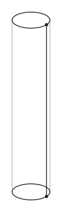
pin.step: three edges, which are the two circles and the seam, and two vertices. The grey lines are the cylinder’s outline, which is not an edge and is not in the file.
Here is its entire solid, 53 records, with the placements’ points and directions elided where they are obvious:
#15 = MANIFOLD_SOLID_BREP('',#16);
#16 = CLOSED_SHELL('',(#17,#50,#59));
#17 = ADVANCED_FACE('',(#18),#45,.T.);            /* the cylindrical side */
#18 = FACE_BOUND('',#19,.F.);
#19 = EDGE_LOOP('',(#20,#30,#37,#38));
#20 = ORIENTED_EDGE('',*,*,#21,.T.);
#21 = EDGE_CURVE('',#22,#24,#26,.T.);            /* the seam: (3,0,0) -> (3,0,30) */
#22 = VERTEX_POINT('',#23);
#23 = CARTESIAN_POINT('',(3.,0.,0.));
#24 = VERTEX_POINT('',#25);
#25 = CARTESIAN_POINT('',(3.,0.,30.));
#26 = LINE('',#27,#28);                          /* along +Z */
#30 = ORIENTED_EDGE('',*,*,#31,.T.);
#31 = EDGE_CURVE('',#24,#24,#32,.T.);            /* top circle, from #24 to #24 */
#32 = CIRCLE('',#33,3.);
#33 = AXIS2_PLACEMENT_3D('',#34,#35,#36);        /* centre (0,0,30), axis +Z */
#37 = ORIENTED_EDGE('',*,*,#21,.F.);             /* the seam again, reversed */
#38 = ORIENTED_EDGE('',*,*,#39,.F.);
#39 = EDGE_CURVE('',#22,#22,#40,.T.);            /* bottom circle */
#40 = CIRCLE('',#41,3.);
#41 = AXIS2_PLACEMENT_3D('',#42,#43,#44);        /* centre (0,0,0), axis +Z */
#45 = CYLINDRICAL_SURFACE('',#46,3.);
#46 = AXIS2_PLACEMENT_3D('',#47,#48,#49);
#47 = CARTESIAN_POINT('',(0.,0.,0.));
#48 = DIRECTION('',(-0.,-0.,-1.));
#49 = DIRECTION('',(1.,0.,0.));
#50 = ADVANCED_FACE('',(#51),#54,.F.);           /* bottom cap */
#51 = FACE_BOUND('',#52,.F.);
#52 = EDGE_LOOP('',(#53));
#53 = ORIENTED_EDGE('',*,*,#39,.T.);
#54 = PLANE('',#55);
#59 = ADVANCED_FACE('',(#60),#63,.T.);           /* top cap */
#60 = FACE_BOUND('',#61,.T.);
#61 = EDGE_LOOP('',(#62));
#62 = ORIENTED_EDGE('',*,*,#31,.T.);
#63 = PLANE('',#64);
Referred to above: 17 records from pin.step
#27 = CARTESIAN_POINT('',(3.,0.,0.));
#28 = VECTOR('',#29,1.);
#29 = DIRECTION('',(0.,0.,1.));
#34 = CARTESIAN_POINT('',(0.,0.,30.));
#35 = DIRECTION('',(0.,0.,1.));
#36 = DIRECTION('',(1.,0.,0.));
#42 = CARTESIAN_POINT('',(0.,0.,0.));
#43 = DIRECTION('',(0.,0.,1.));
#44 = DIRECTION('',(1.,0.,0.));
#55 = AXIS2_PLACEMENT_3D('',#56,#57,#58);
#56 = CARTESIAN_POINT('',(-1.709300165674E-16,-8.51133553645E-18,0.));
#57 = DIRECTION('',(0.,0.,1.));
#58 = DIRECTION('',(1.,0.,-0.));
#64 = AXIS2_PLACEMENT_3D('',#65,#66,#67);
#65 = CARTESIAN_POINT('',(-1.709300165674E-16,-8.51133553645E-18,30.));
#66 = DIRECTION('',(0.,0.,1.));
#67 = DIRECTION('',(1.,0.,-0.));Three faces: a cylinder and two planar caps. Three edges: two circles and one straight line. Two vertices, both on the line. The Euler check: V − E + F = 2 − 3 + 3 = 2. Consistent with a closed shell and no holes.
The count looks wrong for a moment — how does a cylinder have only three edges? — and the answer is the most important idea in this chapter.
11.2 Closed edges and the seam
The top circle #31 is EDGE_: its start vertex and its end vertex are the same record. It is a closed edge — a loop of curve with a single vertex on it, where it begins and ends. The bottom circle #39 is the same, on #22. A circular edge in STEP is nearly always written this way, with one vertex, rather than split into two semicircles.
The cylindrical face #17 is bounded by one loop, #19, with four oriented edges: #21 forwards, #31, #21 backwards, #39. The straight edge #21 appears twice in the same loop, once in each direction. It is a seam: a line up the side of the cylinder where the surface, which is periodic, has been cut so that the face can be bounded by a single loop.
Think of the cylinder’s side as a rectangle of paper rolled into a tube. Its boundary is the two circles — but also the line where the two edges of the paper meet. Walking around the boundary of the flattened rectangle, you go up one side of the seam, around the top circle, down the other side of the seam, and around the bottom. In 3D both sides of the seam are the same line, so the loop traverses #21 twice. The loop is still a single closed cycle; it happens to visit one edge in both directions.
Seams are an artefact of representing a periodic surface with a face that has a boundary, and every cylindrical, conical and toroidal face in this book has at least one. A sphere can avoid them, as the one later in this chapter does, by being bounded at a pole instead. They are legal, universal, and the thing most likely to confuse code that assumes “an edge appears at most once per loop.” The cylindrical face in this file is not two faces; it is one face with a seam.
11.3 The cylinder record
#45 = CYLINDRICAL_SURFACE('',#46,3.);
#46 = AXIS2_PLACEMENT_3D('',#47,#48,#49);
#47 = CARTESIAN_POINT('',(0.,0.,0.));
#48 = DIRECTION('',(-0.,-0.,-1.));
#49 = DIRECTION('',(1.,0.,0.));
CYLINDRICAL_ has a position and a radius. The position’s location is a point on the cylinder’s axis; its axis direction is the axis of the cylinder; its ref_ fixes where the surface’s angular parameter starts. Radius 3. The surface is infinite in both directions along the axis; the face #17 is the portion of it between the two circles.
Note the axis: (-0.,-0.,-1.). This cylinder’s axis points down. The pin’s circles have axes pointing up. Nothing is wrong: the exporter’s kernel built the cylinder one way and its edges another, and the face’s same_ (.T.) and the bound’s orientation (.F.) compose to make the outward normal correct. The surface normal of a cylinder points away from the axis regardless of which way the axis runs; the axis direction affects only the direction of the angular parameter, and so the sense in which loops must run.
11.4 Circles
#32 = CIRCLE('',#33,3.);
#33 = AXIS2_PLACEMENT_3D('',#34,#35,#36);
#34 = CARTESIAN_POINT('',(0.,0.,30.));
#35 = DIRECTION('',(0.,0.,1.));
#36 = DIRECTION('',(1.,0.,0.));
A CIRCLE is a position and a radius. The circle lies in the plane through the position’s location, perpendicular to its axis; it starts at the ref_ and runs counter-clockwise about the axis. So #32 is a circle of radius 3 centred at (0, 0, 30), in the plane z = 30, starting at (3, 0, 30) — which is exactly where vertex #24 sits — and running anticlockwise seen from above. An edge that is the whole circle starts and ends at that vertex. An edge that is part of a circle — an arc — has two different vertices and the arc is the piece of the circle from one to the other in the circle’s direction (or against it, if same_ is .F.).
ELLIPSE is the same with two radii. HYPERBOLA and PARABOLA exist and are almost never seen.
11.5 The hole in the bracket
The bracket is the block with a 6 mm hole down through its centre (Figure 11.2).
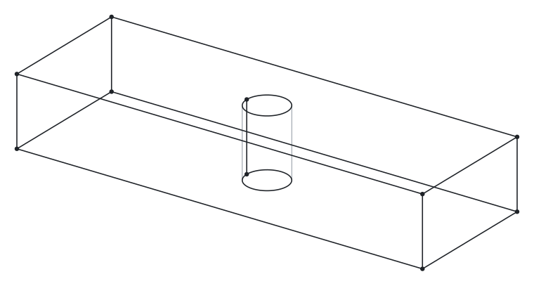
bracket.step: the block’s twelve edges, and the hole’s two circles and seam.
Two faces change and one is added. The top face:
#88 = ADVANCED_FACE('',(#89,#107),#118,.T.);
#89 = FACE_BOUND('',#90,.T.);                     /* outer rectangle */
#90 = EDGE_LOOP('',(#91,#92,#93,#101));
#107 = FACE_BOUND('',#108,.T.);                   /* inner circle */
#108 = EDGE_LOOP('',(#109));
#109 = ORIENTED_EDGE('',*,*,#110,.T.);
#110 = EDGE_CURVE('',#111,#111,#113,.T.);
#111 = VERTEX_POINT('',#112);
#112 = CARTESIAN_POINT('',(27.,10.,10.));
#113 = CIRCLE('',#114,3.);
#114 = AXIS2_PLACEMENT_3D('',#115,#116,#117);
#115 = CARTESIAN_POINT('',(30.,10.,10.));
#116 = DIRECTION('',(0.,0.,-1.));
#117 = DIRECTION('',(-1.,0.,0.));
Referred to above: 37 records from bracket.step
#24 = VERTEX_POINT('',#25);
#25 = CARTESIAN_POINT('',(0.,0.,10.));
#40 = VERTEX_POINT('',#41);
#41 = CARTESIAN_POINT('',(0.,20.,10.));
#47 = EDGE_CURVE('',#24,#40,#48,.T.);
#48 = LINE('',#49,#50);
#49 = CARTESIAN_POINT('',(0.,0.,10.));
#50 = VECTOR('',#51,1.);
#51 = DIRECTION('',(0.,1.,0.));
#70 = EDGE_CURVE('',#24,#71,#73,.T.);
#71 = VERTEX_POINT('',#72);
#72 = CARTESIAN_POINT('',(60.,0.,10.));
#73 = LINE('',#74,#75);
#74 = CARTESIAN_POINT('',(0.,0.,10.));
#75 = VECTOR('',#76,1.);
#76 = DIRECTION('',(1.,0.,0.));
#91 = ORIENTED_EDGE('',*,*,#47,.F.);
#92 = ORIENTED_EDGE('',*,*,#70,.T.);
#93 = ORIENTED_EDGE('',*,*,#94,.T.);
#94 = EDGE_CURVE('',#71,#95,#97,.T.);
#95 = VERTEX_POINT('',#96);
#96 = CARTESIAN_POINT('',(60.,20.,10.));
#97 = LINE('',#98,#99);
#98 = CARTESIAN_POINT('',(60.,0.,10.));
#99 = VECTOR('',#100,1.);
#100 = DIRECTION('',(0.,1.,0.));
#101 = ORIENTED_EDGE('',*,*,#102,.F.);
#102 = EDGE_CURVE('',#40,#95,#103,.T.);
#103 = LINE('',#104,#105);
#104 = CARTESIAN_POINT('',(0.,20.,10.));
#105 = VECTOR('',#106,1.);
#106 = DIRECTION('',(1.,0.,0.));
#118 = PLANE('',#119);
#119 = AXIS2_PLACEMENT_3D('',#120,#121,#122);
#120 = CARTESIAN_POINT('',(0.,0.,10.));
#121 = DIRECTION('',(0.,0.,1.));
#122 = DIRECTION('',(1.,0.,0.));Two bounds. #89 is the rectangle, as in the block. #107 is a loop of one closed edge — the circle of the hole, radius 3, centred at (30, 10, 10). A face with a hole is a face with two loops; the inner loop runs the opposite way to the outer one (clockwise seen from outside), so that the material is still on the left as you walk it. Nothing on the record says which bound is the outer one. The standard offers FACE_ for that purpose, this exporter writes plain FACE_ for both, and a reader must decide from the geometry — typically, the bound whose loop encloses the others in the surface’s parameter space.
The hole’s wall:
#187 = ADVANCED_FACE('',(#188),#199,.F.);
#188 = FACE_BOUND('',#189,.F.);
#189 = EDGE_LOOP('',(#190,#191,#197,#198));
#190 = ORIENTED_EDGE('',*,*,#162,.F.);            /* bottom circle of the hole */
#191 = ORIENTED_EDGE('',*,*,#192,.F.);            /* seam, down */
#192 = EDGE_CURVE('',#111,#163,#193,.T.);
#197 = ORIENTED_EDGE('',*,*,#110,.T.);            /* top circle of the hole */
#198 = ORIENTED_EDGE('',*,*,#192,.T.);            /* seam, up */
#199 = CYLINDRICAL_SURFACE('',#200,3.);
Referred to above: 24 records from bracket.step
#110 = EDGE_CURVE('',#111,#111,#113,.T.);
#111 = VERTEX_POINT('',#112);
#112 = CARTESIAN_POINT('',(27.,10.,10.));
#113 = CIRCLE('',#114,3.);
#114 = AXIS2_PLACEMENT_3D('',#115,#116,#117);
#115 = CARTESIAN_POINT('',(30.,10.,10.));
#116 = DIRECTION('',(0.,0.,-1.));
#117 = DIRECTION('',(-1.,0.,0.));
#162 = EDGE_CURVE('',#163,#163,#165,.T.);
#163 = VERTEX_POINT('',#164);
#164 = CARTESIAN_POINT('',(27.,10.,0.));
#165 = CIRCLE('',#166,3.);
#166 = AXIS2_PLACEMENT_3D('',#167,#168,#169);
#167 = CARTESIAN_POINT('',(30.,10.,0.));
#168 = DIRECTION('',(0.,0.,-1.));
#169 = DIRECTION('',(-1.,0.,0.));
#193 = LINE('',#194,#195);
#194 = CARTESIAN_POINT('',(27.,10.,10.));
#195 = VECTOR('',#196,1.);
#196 = DIRECTION('',(0.,0.,-1.));
#200 = AXIS2_PLACEMENT_3D('',#201,#202,#203);
#201 = CARTESIAN_POINT('',(30.,10.,10.));
#202 = DIRECTION('',(0.,0.,-1.));
#203 = DIRECTION('',(-1.,0.,0.));
The same cylinder-with-seam structure as the pin, turned inside out: this face’s same_ is .F., because the surface normal of a cylinder points away from its axis and the outside of the bracket, at the hole wall, is toward the axis. The top circle #110 is shared: it bounds the top face’s inner loop and the hole wall’s loop, traversed forwards in one and — after the bound flags — backwards in the other, as every shared edge must be.
The bracket has 8 + 2 = 10 vertices (the hole adds one on each circle), 12 + 2 + 1 = 15 edges (two circles and a seam), and 6 + 1 = 7 faces. V − E + F = 10 − 15 + 7 = 2. That is not the 0 you might expect for a solid with a through-hole, and the reason is instructive. The simple formula assumes every face is a disc — one outer loop, nothing inside it. The bracket’s top and bottom faces are rings: each has an inner loop. The general form of the check subtracts them:
\[V - E + F - R = 2(S - H)\]
where \(R\) is the number of inner loops, \(S\) the number of shells and \(H\) the number of through-holes (the genus). For the bracket: 10 − 15 + 7 − 2 = 0 = 2 × (1 − 1). For the block: 8 − 12 + 6 − 0 = 2 = 2 × (1 − 0). For the pin: 2 − 3 + 3 − 0 = 2. Seams, it turns out, do not disturb the count — a seam adds an edge but the face it cuts is still one face with one loop — and this is the form validators actually compute.
11.6 The sphere: a face with no edges
#16 = CLOSED_SHELL('',(#17));
#17 = ADVANCED_FACE('',(#18),#22,.T.);
#18 = FACE_BOUND('',#19,.T.);
#19 = VERTEX_LOOP('',#20);
#20 = VERTEX_POINT('',#21);
#21 = CARTESIAN_POINT('',(3.061616997868E-16,-7.498798913309E-32,-5.));
#22 = SPHERICAL_SURFACE('',#23,5.);
Referred to above: 4 records from sphere.step
#23 = AXIS2_PLACEMENT_3D('',#24,#25,#26);
#24 = CARTESIAN_POINT('',(0.,0.,0.));
#25 = DIRECTION('',(0.,0.,1.));
#26 = DIRECTION('',(1.,0.,0.));A sphere of radius 5 as OCCT writes it with the parameter curves suppressed: one face, one bound, and the bound’s loop is a vertex loop — a loop consisting of a single vertex and no edges. The spherical surface is closed in every direction; there is nothing to trim. But the schema requires a face to have at least one bound, so the face is “bounded” by a degenerate loop at the south pole (the coordinates are (0, 0, −5) with floating-point noise), the only thing in Figure 11.3 that the file records. V − E + F = 1 − 0 + 1 = 2.
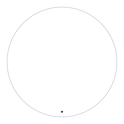
sphere.step: no edges, and one vertex at the south pole. The circle is the sphere’s outline, which the file does not record.
Vertex loops also appear at the apex of a cone and at the poles of a sphere that has been cut by a seam: the degenerate edge where a meridian meets the pole collapses to a point. A VERTEX_ is the standard’s way of saying “this boundary has zero length.”
11.7 The torus: two seams
#17 = ADVANCED_FACE('',(#18),#38,.T.);
#19 = EDGE_LOOP('',(#20,#29,#36,#37));
#20 = ORIENTED_EDGE('',*,*,#21,.F.);
#21 = EDGE_CURVE('',#22,#22,#24,.T.);              /* radius 12: the outer equator */
#29 = ORIENTED_EDGE('',*,*,#30,.F.);
#30 = EDGE_CURVE('',#22,#22,#31,.T.);              /* radius 2: a meridian */
#36 = ORIENTED_EDGE('',*,*,#21,.T.);
#37 = ORIENTED_EDGE('',*,*,#30,.T.);
#38 = TOROIDAL_SURFACE('',#39,10.,2.);
Referred to above: 17 records from torus.step
#18 = FACE_BOUND('',#19,.T.);
#22 = VERTEX_POINT('',#23);
#23 = CARTESIAN_POINT('',(12.,-2.939152317954E-15,-4.898587196589E-16));
#24 = CIRCLE('',#25,12.);
#25 = AXIS2_PLACEMENT_3D('',#26,#27,#28);
#26 = CARTESIAN_POINT('',(0.,0.,-4.898587196589E-16));
#27 = DIRECTION('',(0.,0.,1.));
#28 = DIRECTION('',(1.,0.,-0.));
#31 = CIRCLE('',#32,2.);
#32 = AXIS2_PLACEMENT_3D('',#33,#34,#35);
#33 = CARTESIAN_POINT('',(10.,-2.449293598295E-15,0.));
#34 = DIRECTION('',(-2.449293598295E-16,-1.,0.));
#35 = DIRECTION('',(1.,-2.449293598295E-16,0.));
#39 = AXIS2_PLACEMENT_3D('',#40,#41,#42);
#40 = CARTESIAN_POINT('',(0.,0.,0.));
#41 = DIRECTION('',(0.,0.,1.));
#42 = DIRECTION('',(1.,0.,-0.));A torus is periodic in both directions, so a single face on it needs two seams: one around (the equator, #21, radius 12 = 10 + 2) and one across (a meridian, #30, radius 2). Both are closed edges on the single vertex #22 where they cross, and both appear twice in the loop (Figure 11.4).
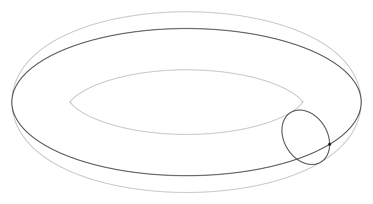
torus.step: the equator and a meridian, the two seams, crossing at its only vertex. The grey curves are the torus’s outline.
One face, two edges, one vertex: V − E + F = 1 − 2 + 1 = 0, which for once is the textbook genus-1 answer, because here every edge is a seam and they cancel.
TOROIDAL_ has a position, a major_ (centre to tube centre, 10) and a minor_ (tube, 2).
11.8 The cone
#33 = B_SPLINE_CURVE_WITH_KNOTS('',1,(#34,#35),.UNSPECIFIED.,.F.,.F.,
        (2,2),(0.,1.),.PIECEWISE_BEZIER_KNOTS.);
#34 = CARTESIAN_POINT('',(5.,0.,0.));
#35 = CARTESIAN_POINT('',(2.,0.,10.));
#44 = CONICAL_SURFACE('',#45,5.,0.291456794478);
#45 = AXIS2_PLACEMENT_3D('',#46,#47,#48);
#46 = CARTESIAN_POINT('',(0.,0.,0.));
#47 = DIRECTION('',(-0.,-0.,-1.));CONICAL_ has a position, a radius at the position’s location, and a semi_ in the context’s plane angle unit, here radians. This cone has radius 5 at z = 0 and half-angle 0.2915 rad (16.7°): over 10 mm of height it narrows to radius 2, and the axis, again, points down (Figure 11.5).
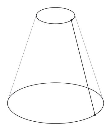
cone.step: two circles, and a seam written as a degree-1 B-spline, which draws as the straight line it is. The grey lines are the cone’s outline.
The seam of this cone is a straight line from (5, 0, 0) to (2, 0, 10) — and the exporter has written it not as a LINE but as a degree-1 B-spline with two control points. It is a line in everything but name. This happens when a kernel has represented a curve internally as a spline and does not bother to recognise that it is analytic on the way out. A reader that special-cases LINE and CIRCLE and treats everything else as “free-form” will call this a free-form edge. It is not wrong to do so; it is just less informative. The next chapter takes the B-spline record apart.
11.9 The analytic vocabulary
Most analytic curves and surfaces in Part 42 are positioned by an AXIS2_ — a point, an axis (the local Z) and a reference direction (the local X) — and then given one or two numbers. The swept surfaces at the foot of the table are the exception: they carry a curve and a direction instead.
Surfaces
| Entity | Extra attributes | Position means |
|---|---|---|
PLANE |
— | a point on the plane; axis = normal |
CYLINDRICAL_ |
radius |
a point on the axis; axis = cylinder axis |
CONICAL_ |
radius, semi_ |
a point on the axis where the radius applies |
SPHERICAL_ |
radius |
the centre |
TOROIDAL_ |
major_, minor_ |
the centre; axis = the ring’s axis |
SURFACE_ |
swept_, axis_ |
a curve rotated about an axis (an AXIS1_) |
SURFACE_ |
swept_, extrusion_ |
a curve swept along a vector |
Curves
| Entity | Attributes | Notes |
|---|---|---|
LINE |
pnt, dir (a VECTOR) |
infinite; the point at parameter \(t\) is pnt + \(t\) × dir, so the parameter is a distance only when the vector’s magnitude is 1 |
CIRCLE |
position, radius |
in the position’s XY plane, CCW about its axis |
ELLIPSE |
position, semi_, semi_ |
|
TRIMMED_ |
basis_, trim_, trim_, sense_, master_ |
a piece of another curve, trimmed by points or parameters |
COMPOSITE_ |
segments, self_ |
several curves end to end |
POLYLINE |
points |
straight segments through a list of points |
TRIMMED_ is the record where the typed wrapper of Chapter 4 appears most: trim_ and trim_ are each a set of one or two values, each a SELECT of a CARTESIAN_ or a PARAMETER_ — a writer may give the point, the parameter, or both, which is why they are parenthesised — so a curve trimmed by parameter looks like TRIMMED_. Inside a B-rep, trimming is done by the topology — the edge’s vertices — and TRIMMED_ is rare; it appears in wireframes, in sketches, and in PMI annotation geometry.
The sphere’s pole is at (3.061616997868E-16, -7.498798913309E-32, -5.). The torus’s vertex is at (12., -2.939152317954E-15, -4.898587196589E-16). These are zeros, written as the kernel computed them — the residue of a cosine of 90° that came out as \(6 \times 10^{-17}\) rather than 0. They are harmless, they are everywhere, and they are why comparing coordinates for equality is never the right operation on STEP geometry; comparing within a tolerance is, and the file’s uncertainty is the natural starting value for one.
Analytic surfaces are positioned by an axis placement plus one or two radii or an angle; their normals point away from the axis (cylinder, cone), outward from the centre (sphere), away from the tube’s centre circle (torus, so inward on the inside of the ring), or along the axis (plane), and same_ reconciles that with the solid. A periodic surface that has been cut is bounded by a single loop that traverses each seam edge twice, once in each direction. A full-circle edge is closed: one vertex, start = end; an arc has two. A surface with nothing to trim gets a vertex loop. Lines sometimes arrive as degree-1 B-splines.